|
The two extra Pipeline stages of the Athlon K8 (by Hans de Vries)
Raising the IPC of the Athlon core
The upcoming AMD Hammer family promises a significant increase in performance compared with the current generation of Athlon processors. Some of the increase comes from the low latency on chip memory controller, some of it comes from the extra architectural registers of the x86-64 instruction set and some comes from a number of new features that improve the ability of the Hammer micro-architecture to recognize a higher IPC ( Instructions executed Per Clock) than previous generation micro-architectures. Here we look into some depth into the latter.
Stretching the (Integer) pipeline from 10 to 12 stages Two new pipeline stages are added to the pipeline. They are inserted directly after the stage where the x86 instructions have been either decoded, ( In case of the simpler 'RISC' like x86 instructions), or have started the micro code program from the micro code ROM. ( In the case of the more complex 'CISC' like x86 instructions) The new pipeline stages thus receive a stream of decoded instructions, either from the decoders or from the micro code ROM.
Keeping up with the decoder speed. The instruction fetch unit can catch 16 instructions bytes per cycle. On average good for 5 instructions or so. Branches that have to be predicted will insert a single cycle bubble in the pipeline. The decoders can pick 3 instructions per cycle from the instruction stream. Such a maximum throughput of 3 instructions per cycle may actually be approached with newer 'branch-reduced' software and with not much else to stop the decoders if it weren't for the rest of the pipelines. The actual average throughput of the execution pipelines is actually a lot less then 3 instructions per cycle. Data dependencies, Cache latencies and misses, Resources conflicts, all add on to throttle the instruction throughput.
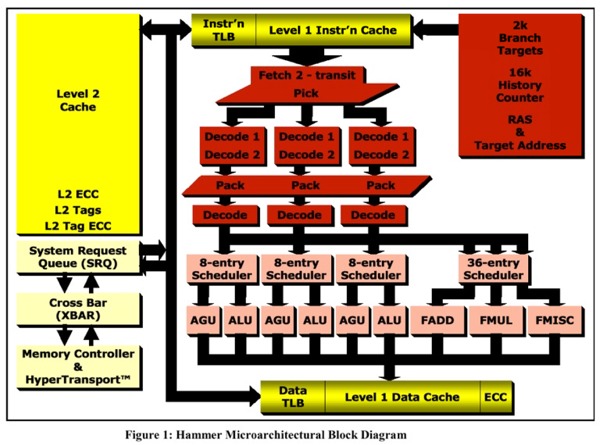
The Hammer diagram from Fred Weber's 2001 Micro Processor Forum. The new stages are the 'Pack' stage and the following 'Pack/decode' stage
'Inter-Instruction Decoding' The stage after the decoders is there for the right place to start. One typically might start with a small queue to buffer the incoming decoded instructions without having to stop the stream at every hick-up. Such a small queue then gives one the opportunity to look at a somewhat larger window of instructions and examine their type and inter-dependencies. This type of further 'decoding-after-decoding' might be called 'inter-instruction' decoding. It analysis a set of multiple instructions and their relations and provides a surprisingly large number of opportunities for performance improvements over the current Athlon K7.
(Don't) keep your lane Instructions stay on their lane in the Athlon K7. Once picked from the instruction byte stream and send to one of the 3 decoders they do no change lanes anymore. They are scheduled, executed and retired on the same lane. The Pack stage in the Hammer core however can switch instructions from one lane to another.
Ways to increase the IPC of the K7 Athlon We'll discuss a number of methods that may be implemented in the new stages that altogether can significantly increase the amount of parallelism that the Athlon core can recognize and process. These methods are typically based on 'Inter-Instruction-Decoding' and do not need any knowledge of actual data-contents of registers and memory or the final addresses used for memory accesses:
(1) Improved Efficiency when Integer code is mixed with FP/MMX/SSE code. (2) Switch between the 3 Lanes to separate non dependent operations. (3) Bypassing Moves and/or merging them into to 3-op RISC instructions. (4) Accelerated Access to Stack Data by displacement accumulation. (5) Out-of-Order processing of Stack and Stack Frame Accesses.
Beware: "May be implemented" Before we start, Let me quote the comments added to the new pipeline stages in AMD's document:
" The pipelines front-end greater degree of instruction packing from the decoders to the execution pipe schedulers."
" On the other end of the performance equation are the key features that improve the ability of the Hammer micro-architecture to recognize a higher IPC ( Instructions executed Per Clock) than previous generation micro-architectures." That's about it.... AMD did not elaborate on how it achieves these goals. What we do here is describe the main candidates for realizing a higher IPC that can be implemented at this stage of the pipeline. What AMD has implemented or what is being implemented by Jay Pickett's K9 design team is kept undisclosed by AMD. It does show however that there is still a lot of headroom to significantly improve the Athlon's Performance.
|
|
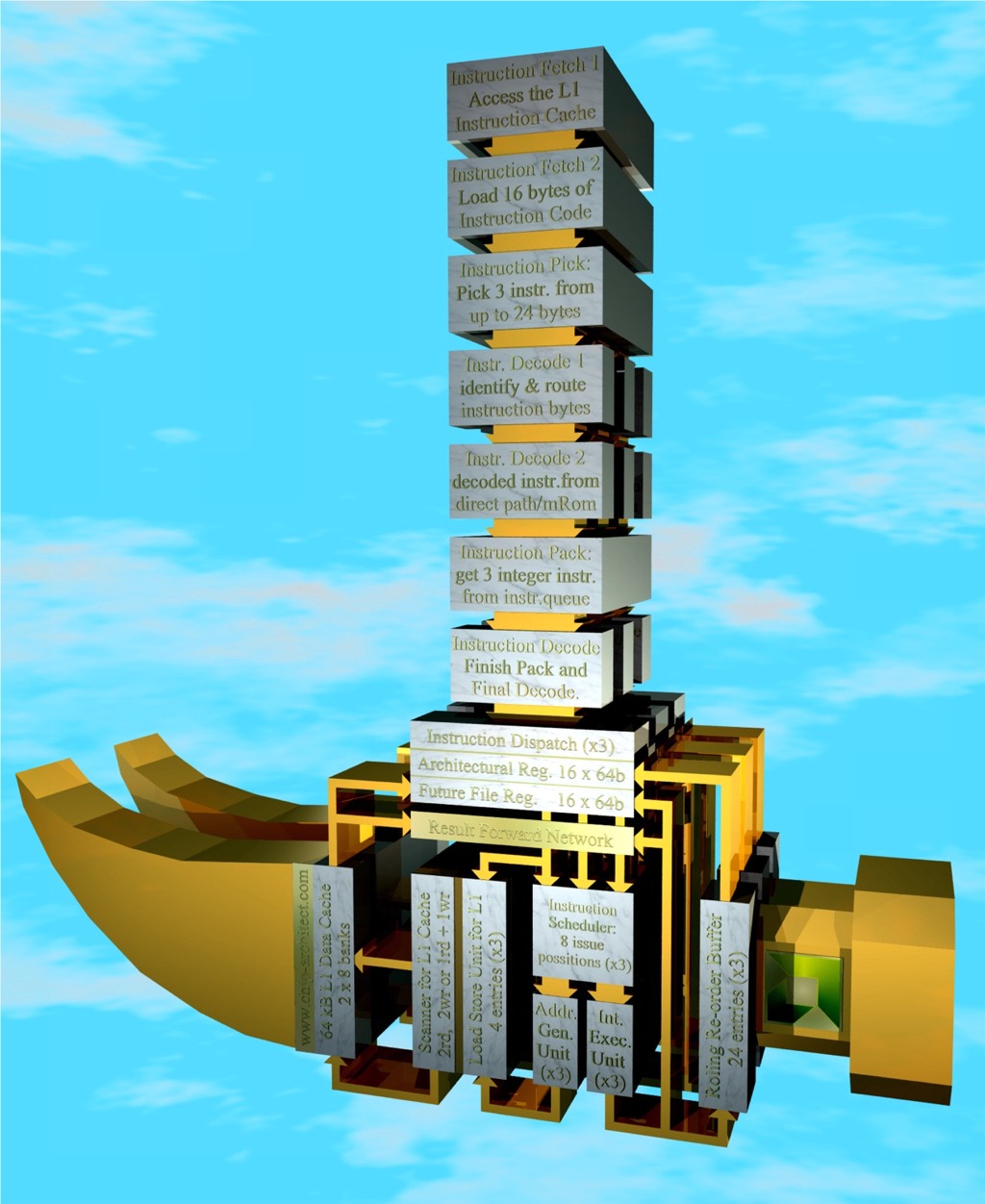
For a starter: The Athlon Hammer Pipeline
Download the 3D Ray Tracing Model (PovRay 3.5) Click here to download a zip file with our 3D ray-tracing model of the AMD Hammer Athlon. You can download the latest release candidate of PovRay for windows here. Unzip the model file in an arbitrary directory. Start PovRay for windows. Open the Athlon.pov file. Optionally choose the resolution of the result image and click the RUN button to render the Image. You can change the camera position to different view points.
|
|
IPC improvement option 1 Improved Efficiency when Integer code is mixed with FP/MMX/SSE code.
A story of two pipelines The Athlon has both an Integer and a Floating Point/MMX/SSE pipeline. Both pipelines are configured to handle the maximum of three instructions that the decoders can provide from the start to the end. Both of them have their own register files, schedulers, execution units. Both pipelines can retire 3 instructions per cycle: The Integer Reorder Buffer can retire 3 Integer result values per cycle to the Integer Architectural Register File while the FP/MMX/SSE Reorder Queue can retire 3 result tags per cycle to the FP/MMX/SSE Architectural Register Tag File.
The Improvement The Athlon K7's IPC is unnecessary limited because its decoded instructions do not change lanes. If a set of 3 instructions is partly Integer code and partly FP/MMX/SSE code then only 1 or 2 Integer Instructions are send to the Integer Pipeline and, visa versa, only 2 or 1 instructions are send to the FP/MMX/SSE pipeline. The Athlon K8's "Pack" stage may look to more then one set of 3 instructions in a small decoded instruction queue and select up to 3 Integer Instructions for the Integer Pipeline plus up to 3 FP/MMX/SSE instructions for the FP/MMX/SSE pipeline simultaneously.
|
|
IPC improvement option 2 Switching Instructions between the 3 Lanes to separate non dependent operations.
Waiting for your turn. The Athlon K7 and Athlon K8 have three independent Integer execution units each accompanied with its own scheduler. Each scheduler can hold six (K7) or eight (K8) instructions waiting to be executed. An instruction can receive its source operands from each of the three execution units. Instructions waiting in one scheduler however can only be executed by the integer execution unit belonging to that particular scheduler, not by any of the other two. The instruction has to wait for it's turn even if one of the other integer execution units is idle. This means that two instructions that can in principle be executed in parallel, can't do so if they are send to the same scheduler.
The Improvement. The Athlon K7 sends an instruction to a certain scheduler only depending on the program order. It's position is determined at the 'Pick' stage that selects up to three instructions from up to 24 instruction bytes. The instruction stays in the same lane until it is retired. The Athlon K8's "Pack" stage that selects the 3 integer instructions may look at data-dependencies with immediately preceding set (s) of 3 instructions. It may then decide to switch lanes to route independent instructions to different scheduler as much as possible. The theoretical maximum speed improvement is about 66% (with the remark that this will occur rather seldom) |
|
IPC improvement option 3 Bypassing Moves and/or merging them into to 3-op RISC instructions.
Costly Moves. The x86 instruction format uses operand 'destructive' operations. One of the two source operands is overwritten with the result of the operation. This unlike RISC operations where 3 different registers can be specified for the two source operands and the destination operand. The result is that moves are being frequently used in the average program. The Athlon K7 has no special provisions for the (Integer) moves. The original K7 Floating Point Pipeline does much better in this respect: It can eliminate up to three FXCH per cycle. (FXCH swaps the top the FP stack with any of the other FP stack entries.
The Improvement. The Athlon K7 does not optimize moves. Moves cause an extra cycle latency for a following dependent instruction. Moves occupy an entry in the schedulers and keep an execution unit busy for a cycle. The Athlon K8's "Pack" stage may examine a window of instructions in a small decoded instruction queue for Moves and consuming operations. Operations are 'Non-Destructive' if they do not overwrite the source operand provided by the Move and 'Destructive' if they do. Non-destructive operations can 'Bypass' the Move if they are provided with the Source Tag of the Move instead of the Destination Tag. Destructive operations may use the same method. A Move may be discarded altogether when it can be matched with a 'Destructive' operation.
An example: The following code may be replaced:
R9 => R12; // MOVE R14 = R14 + R12; // Non destructive ADD (for R12) R12 = R12 & R15; // Destructive AND in (for R12)
With this code:
R14 = R14 + R9; R12 = R9 & R15;
An Out-Of-Order processor in general maintains a recent speculative state history of it's Architectural Registers. All the recent values that a certain Architectural Register had can be retrieved from the Renamed Register File. The oldest available version is found in the register that contains the retired value. The situation is a little bit different in the Integer Execution Core of the Athlon with it's Future File but actually not that much. The example above doesn't work if the value of R9 is not retrievable anymore from either the Architectural Register File, The Future File or from one of the result busses.
Example 2: Here we include a version number with the Architectural Registers
R91 => R121; // MOVE R92 = R91 - R111; // Subtract that overwrites R9 R142 = R141 + R121; // Non destructive ADD (for R12) R122 = R121 & R92; // Destructive AND (for R12)
The code above may be replaced with this code:
R92 = R91 - R111; // Subtract that overwrites R9 R142 = R141 + R91; // ADD that uses previous value of R9 R122 = R91 & R92; // AND that uses both values of R9
The last instruction: R122 = R91 & R92 is dispatched and accesses the Architectural and Future Register File on address 9 for both source operands on two read ports simultaneously. It compares the rename tags and may find the R91 value for instance in the Future File. It won't find the value of R92 in either of these files because the subtractions has yet to be scheduled and executed. Our instruction will proceed to an issue position in the scheduler with only the result and waits there until it can grab R92 from one of the result busses. The combined latency of the scheduler and the integer execution unit provide a window that guarantees that the value of R91 is still available and has not been squeezed out of the future file yet.
We can conclude that:
1) Moves may be removed from the instruction stream if the operation is found that overwrites the target register of the move. And, There are no instructions between the two that can change the program-flow. And, The distance between an instruction that overwrites the source register of the move and the one that overwrites the target register of the move is small enough to guarantee by design that the value of the source register of the move is still available in the out-of-order core.
2) Moves may be bypassed by operations that use the target register of the move if there are no instructions between the two that can change the program-flow. And, The distance between an instruction that overwrites the source register of the move and the one that uses the target register of the move is small enough to guarantee by design that the value of the source register of the move is still available in the out-of-order core.
3) Operations that bypass the move have one of their the Source Register Number and Tag changed from the destination of the Move to the source of the Move. The Tag is a simple incremental value that is incremented each time when 3 instructions are "Packed" from the decoded instruction stream.
|
|
IPC improvement option 4 Accelerated Access to Stack Data by displacement accumulation.
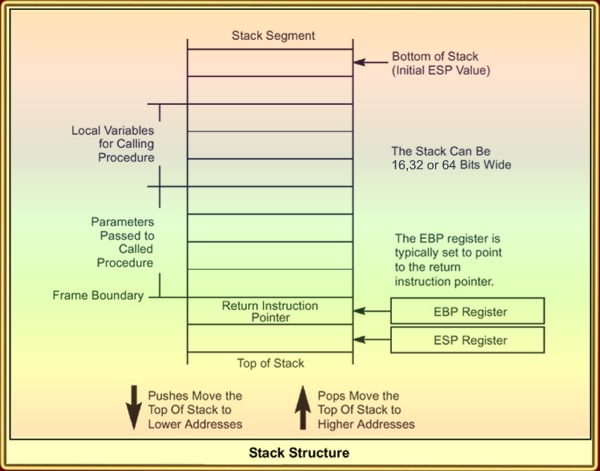
The Importance of the Stack Frame. The Stack is of central importance in any block oriented language such as C. One might say that a processor that has more registers basically uses these registers to hold values that would otherwise live on the stack. It is beneficial to have more on chip registers. The hammer may get a 10% to 15% performance gain from its additional registers. It equally beneficial to improve the access to and from the stack itself.
The Stack in x86. The Accesses to the stack are handled by the stack-pointer ESP and the stack frame pointer EBP. The latter accesses a function local variables and parameters passed to the procedure with immediate displacements defined by the instruction code. The ESP handles state save and restore via Stack Pushes and Pops. The Pushes and Pops decrement and increment the ESP register by 2,4 or 8 depending on the data size mode: 16, 32 or 64 bit. (64 bit is Hammer only). EBP and ESP are related in the sense that the CALL, RET protocol requires that the ESP contents is moved to EBP during a CALL, and visa versa, the EBP contents is moved to ESP during a RET. The CISC functions ENTER and LEAVE set up and retrieve stack frames automatically including the above mentioned moves. The contents of EBP will typically be hold constant during the procedure CALL while the ESP will change with every PUSH and POP.
A first Improvement. The Athlon K7 serializes all Pushes and Pops during state save and restore because each one is dependent on the other. A mechanism that accumulates displacements during 'inter-instruction-decoding' can remove the data dependencies. The Address Generators in the K7 and K8 all have a displacement input that adds an arbitrary displacement to the address. This displacement addition thus comes for free. An 'accelerated ESP' register may be maintained in parallel to the Architectural and Future register file. Only the ESP values are stored to this register that cannot be derived from previous ones by displacement accumulation during instruction decoding. All other ESP based instructions may use this register instead of the regular one. The dispatch units send the 'accelerated' ESP register value plus the accumulated displacement to the scheduler which passes it to its AGU (Address Generator Unit) when it determines that the instruction can be executed. Up to 3 pushes and pops can now be handled per cycle instead of one only to be limited by the scanner of the Load/Store unit that handles a maximum of 2 accesses per cycle to the L1 Data Cache.
|
|
IPC improvement option 5 Out-of-Order processing of Stack and Stack Frame Accesses.
The Importance of Out of Order processing. Out of Order processing can keep the execution units busy even while some instructions are waiting for data coming from the cache or other instructions. OOO processing is possible because an instruction set uses hard-coded reverences to registers like R12 and R9. The processor can check data dependencies before it executes the instructions. A chicken and Egg situation however arises with reverences to values stored in memory. The exact address are not know until the instructions are executed. An OOO processor however needs to know the addresses in advance to be able to check the data-dependencies so that it can schedule the instructions for executions. Some architectures (EV6, Pentium 4) try to predict data dependencies between memory accesses in general. The Pentium 4 uses its Replay Unit to re-execute miss-predicted accesses plus all dependent operations. (The Replay Unit is one of the basic corner stones of the NetBurst architecture intended to support all kind of data-prediction methods that are intended to go beyond the shortest execution path provided by dataflow analysis)
The Improvement. A deterministic method for OOO processing of stack-frame memory access with both ESP and EBP is possible with an extension of the displacement accumulation method described in option 4. An accelerated version of both ESP and EBP is maintained in parallel with the Architectural and Future register file. Only values of ESP and EBP are stored in these registers that cannot be derived from previous ones by the accumulation of displacements and moves between EBP and ESP . Furthermore: The moves between ESP and EBP offer an opportunity to keep equal values in ESP and EBP. All other ESP and EBP based instructions may use these registers instead of the regular once. The dispatch units send the 'accelerated' ESP or EBP register value plus the accumulated displacement to the scheduler which passes it to its AGU (Address Generator Unit) when it determines that the instruction can be executed. Up to 3 arbitrary stack-frame accesses can now be handled per cycle.
Furthermore. The dispatch units also send the accumulated displacement to the LS1 Load/Store unit that normally only receives write data (if available) from the dispatch unit. This now solves the chicken an egg problem: The data dependencies for stack accesses can be resolved before the instructions are executed. The accesses are non dependent if the 'accelerated' ESP or EBP registers are used and the accumulated displacements are different. The LS scanner that selects loads and stores from the three LS sub units for execution in the L1 Data Cache can now for instance prioritize Loads over Stores.
|
|
Conclusion
The (optional) performance improvements listed above show that a significant performance improvement can be achieved over the Athlon K7 core. A core that was after-all conceived and implemented in record time. All these improvements are further very 'cheap' in terms of transistor count and power dissipation. They are chosen so that they can be realized within the extended pipeline of the K8 that includes two extra pipeline stages between instruction decoding and dispatching.
Hans de Vries
|
![]()
![]()